


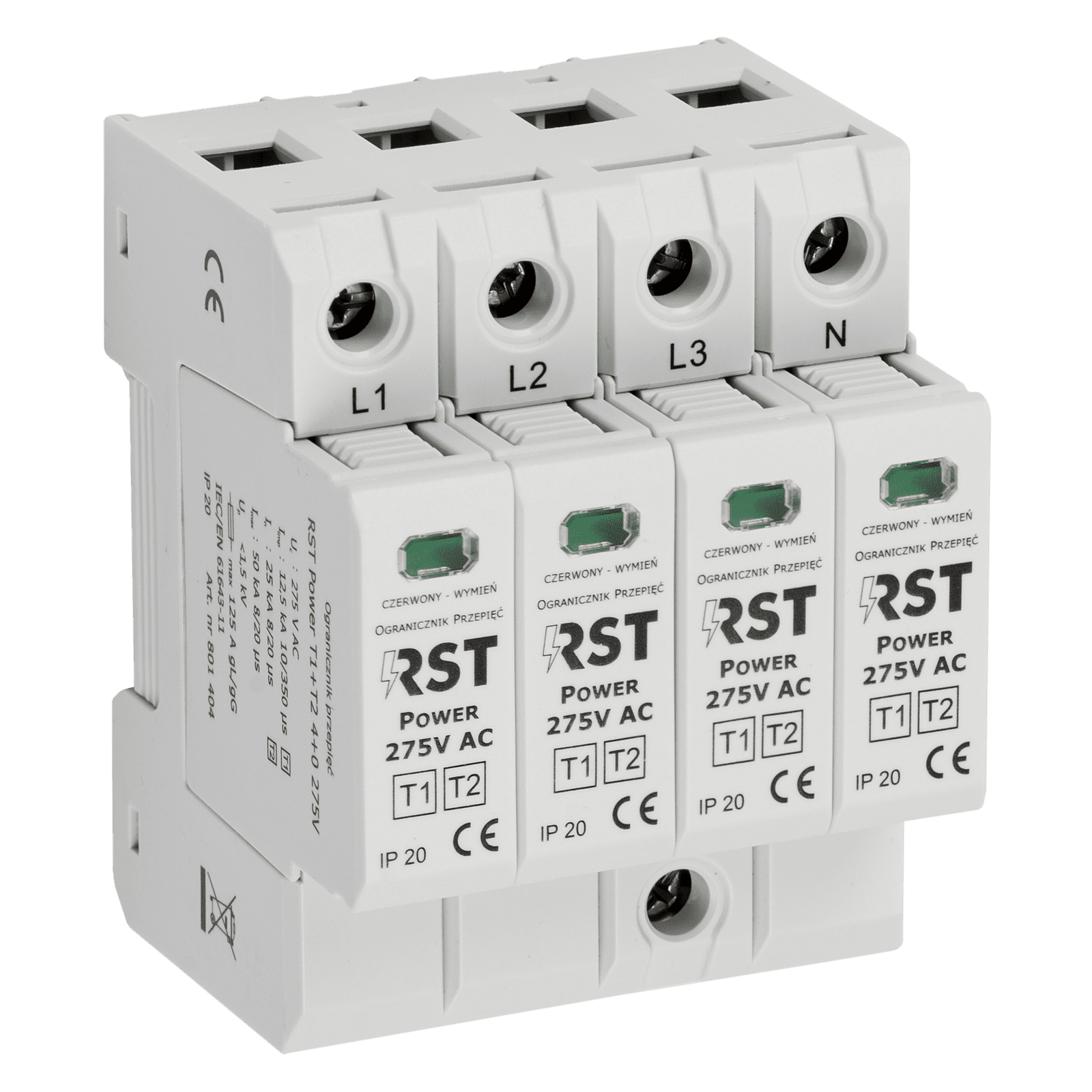
Surge arrester – RST Power – AC 3-phase Type 1+2 – 4+0 275V
| Manufacturer | |
|---|---|
| Weight | 0,466 kg |
| CN | 85354000 |
Gross
Product details
| Manufacturer | |
|---|---|
| Weight | 0,466 kg |
| CN | 85354000 |
RST Power Surge Protector T1+T2 4+0 275V (FM)
The RST Power Surge Protector T1+T2 4+0 275V (FM) is a high-quality, combined Type 1+2 protector designed to safeguard three-phase TNS installations (230/400 V). It provides comprehensive protection against the effects of partial lightning currents as well as induced and switching surges. With a built-in remote signalling contact (FM version), it can be integrated with monitoring systems to enhance overall installation safety.
Key features of the RST Power Surge Protector T1+T2 4+0 275V (FM):
- Combined Type 1+2 protection: Delivers full protection for electrical installations against partial lightning currents and internal surges.
- High discharge capacity: Effectively diverts surge currents, with a lightning impulse current (10/350 µs) Iimp of 12.5 kA and a maximum discharge current (8/20 µs) Imax of 50 kA.
- Remote fault signalling (FM version): Equipped with a volt-free changeover contact (NO/NC – SPDT) that signals when the module needs replacement, which is essential for systems requiring continuous supervision.
- Low voltage protection level: Provides a voltage protection level (Up) below 1.5 kV, effectively protecting sensitive end devices from damage.
- Visual status indication: Each module features an optical status indicator (green – OK, red – fault), allowing quick and easy assessment of the protector’s condition.
Who is this a good choice for?
The RST Power T1+T2 surge protector in FM version is an essential protective component for residential, commercial, and industrial installations. It is an ideal choice for installers and facility owners who prioritize safety and reliability of their electrical systems. The version with a remote signalling contact is particularly recommended for main distribution boards where continuous monitoring of protection status is required, such as public buildings, manufacturing plants, and server rooms.
| Parameter | RST Power T1+T2 4+0 275V | RST Power T1+T2 4+0 275V FM |
|---|---|---|
| SPD classification according to PN-EN 61643-11 | ||
| SPD design type | Type 1+2, combined, with a voltage-cutting element | |
| Rated AC voltage (Un) (V) | 230/400 | |
| Maximum continuous operating AC voltage (50/60Hz) (Uc) (V) | 275 | |
| Connection configuration | CT1 4+0 | |
| Network type | 3-phase TNS | |
| Lightning current (10/350 µs) L/N – PE (Iimp) (kA) | 12,5 | |
| Maximum discharge current (8/20 µs) L/N – PE (Imax) (kA) | 50 | |
| Nominal discharge current (8/20 µs) L/N – PE (In) (kA) | 25 | |
| Voltage protection level L/N – PE (Up) (kV) | < 1,5 | |
| Voltage protection level L – N (Up) (kV) | < 2,0 | |
| Temporary overvoltages (TOV) (Ut) | 393 V/5 s; 1453 V/200 ms | |
| AC follow-current interruption capability (Ifi) | 1000 Arms/255 V | |
| Leakage current at Uc (IPE) | none | |
| Response time (ta) (ns) | < 100 | |
| Maximum protective device current at which the SPD does not require additional protection | 125 A gL/gG | |
| Cross-section of connection conductors solid/flexible (mm²) | 6 – 35 / 6 – 25 | |
| Cross-section of connection conductors (AWG) | 9 – 2 / 9 – 3 | |
| Optical indication operational / faulty | green / red | |
| Operating temperature range (T) (°C) | -40 … +70 | |
| Permissible relative humidity (RH) (%) | 90 | |
| Enclosure material/Flammability class according to UL 94 | thermoplastic / V0 | |
| Enclosure protection rating (IP) | IP 20 | |
| Enclosure dimensions (mm) | 72 x 90 x 67 (4TE) | |
| Mounting | 35 mm rail | |
| Remote fault signaling contact parameters (FM version) | ||
| Maximum contact load | Not applicable | AC: 250 V/0,5 A; 125 V/3 A
DC: 250 V/0,1 A; 125V/0,2A |
| Type of contacts | Not applicable | NO/NC – SPDT |
| Maximum conductor cross-section (mm²) | Not applicable | 1,5 |
| Maximum tightening torque (Nm) | Not applicable | 0,25 |
| Catalog number | ||
| Catalog number | 801 404 | 801 409 |
Official distribution